Tri State Area
Makerspace at the Fulton School
Makerspace Project
One day I got super bored and didn’t have a project to do. After spending nearly the entire time trying to find what to do, I eventually found two pencils and a random ball of light blue yarn and decided to use them to knit. I decided not to do a particular design, but it will be finished when the yarn runs out. This project is very relaxing and fun to do. It provides a nice break from stressful stuff. So far, I think I’m halfway through the yarn or close to halfway. By doing this project I learned that it’s really easy to find the basic materials for knitting and starting.
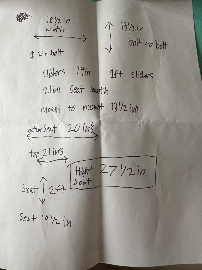
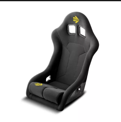
Fiat 500 seat upgrade
This week in maker’s space I worked on planning a seat upgrade for my car, which is a Fiat 500. The new seat is made in Italy and the company is Italian. It is a bucket seat and I want to upgrade to it because it’s cooler and safer. I made sure to measure the dimensions and the height of the seat compared to the old seat. I also investigated the bolt sizes to make sure they fit the brackets. I figured out which tools I would need. Most of the bolts are 16 mm and 10 mm. I have all of the information I need to order the seat when I have the money to buy it.
Monuments from around the world,
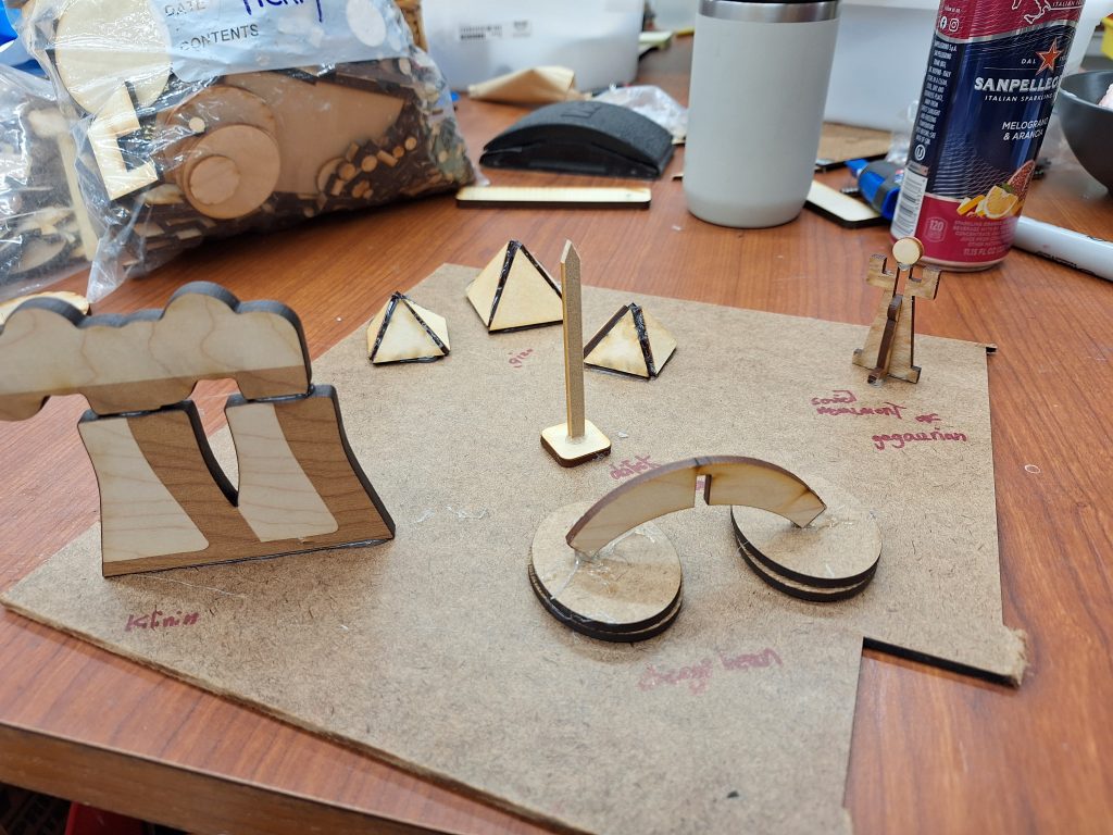
I made some wooden replicas of some monuments from around the world.
I used some scraps from the scraps pile and hot glued things together.
I made the pyramids of Giza, the Chicago bean the Kilianan nuclear powerplant, and the Gagarin monument. Even the Obelisk of Piazza Navona.
iPhone 5 teardown display
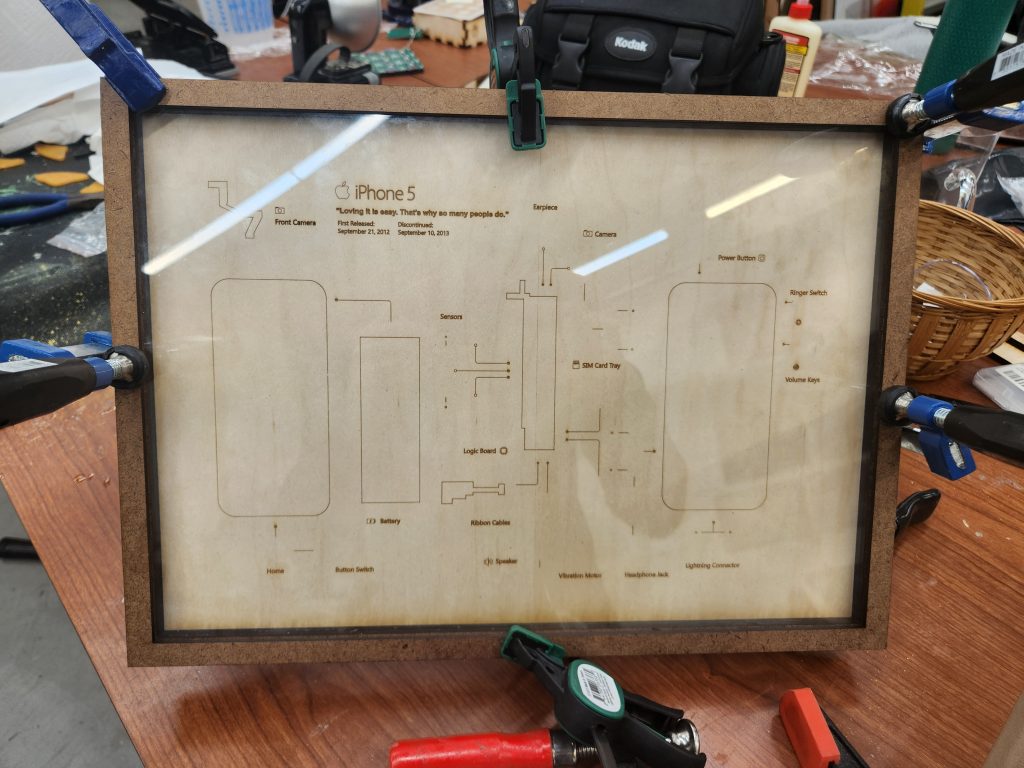
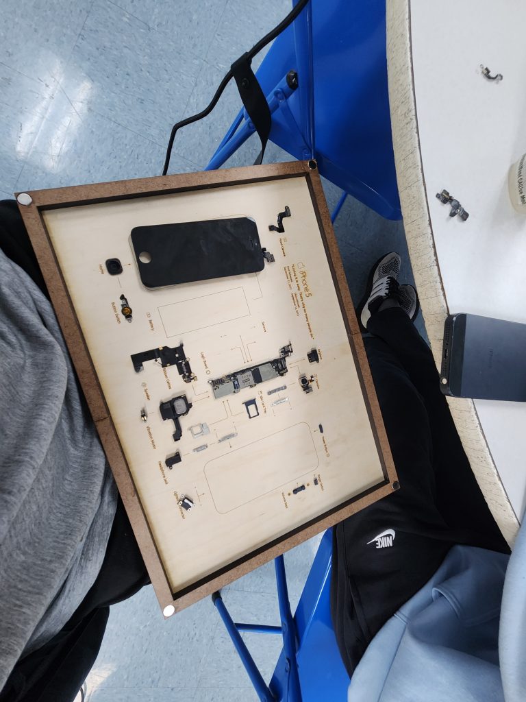
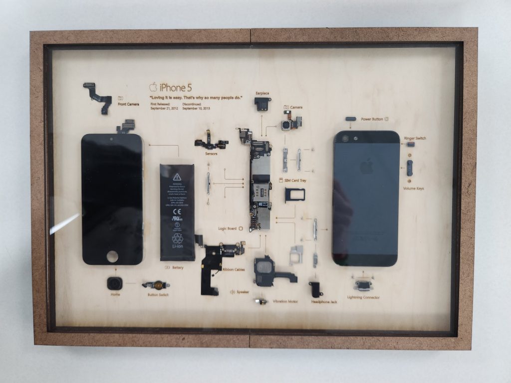
For the 2024 global interim I did a project I had been wanting to do for a while, a teardown display of an iPhone. Recently the Makerspace received a donation of several old Apple products, one of them being an iPhone 5.
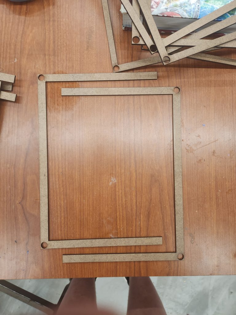
I spent a while trying to find a good template that I could transfer to an .svg file for laser cutting. After doing this I designed a magnetic frame assembly that would let me take the whole frame apart.
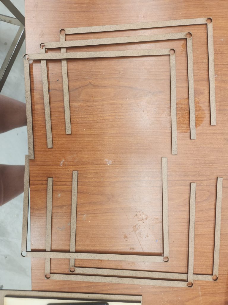
The frame consists of three pieces, a backboard, mid frame, and top frame. The teardown display sits in between the backboard and mid frame while a piece of clear acrylic sits between the mid and top frames.
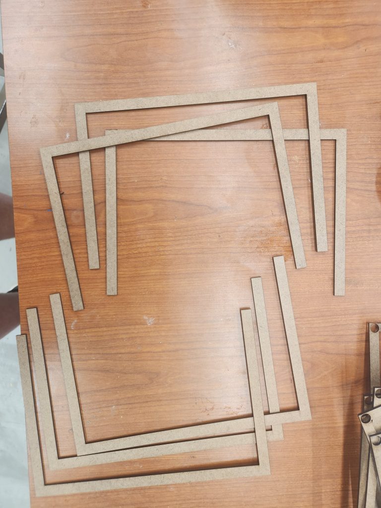
My original design had the individual layers of the frame cutout in two parts, while seeming like a good idea at first, I later realized that the way I designed it wasn’t all that good, resulting in a more painful assembly process. This design has since been fixed for anyone willing to replicate the project in the future.
Disassembly of the iPhone was a much less painful experience, with help from Damien I was able to get it all taken apart and glued onto the board.
This project fits into the global theme of this week’s interim since it displays all of the globally sourced internals of an iPhone, Japanese batteries and Cameras, Taiwanese silicon, American glass, and Korean processors all put into a phone designed by Apple in California.
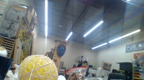
Amazing Abaca ball
I made an abaca ball, which is from the Philippines. Abaca thread is made from an abaca plant. Abaca plants are native to the Philippines. It also takes several months to be ready for harvest. Long story short, I don’t have any abaca. You may be asking, “how did you make an abaca ball without any abaca thread?” the answer is, I didn’t. Instead of giving up, I improvised by using Millie’s idea which was coating string or yarn in glue and wrapping it around a balloon. After a day, you would pop the balloon. The sting or yarn would stay put because it was covered in dried glue, therefore keeping the string or yarn in place.
Link to info: Food And Agriculture Organization of the United Nations: Future Fibers: Abaca
I discovered abaca balls from Pintrest
“
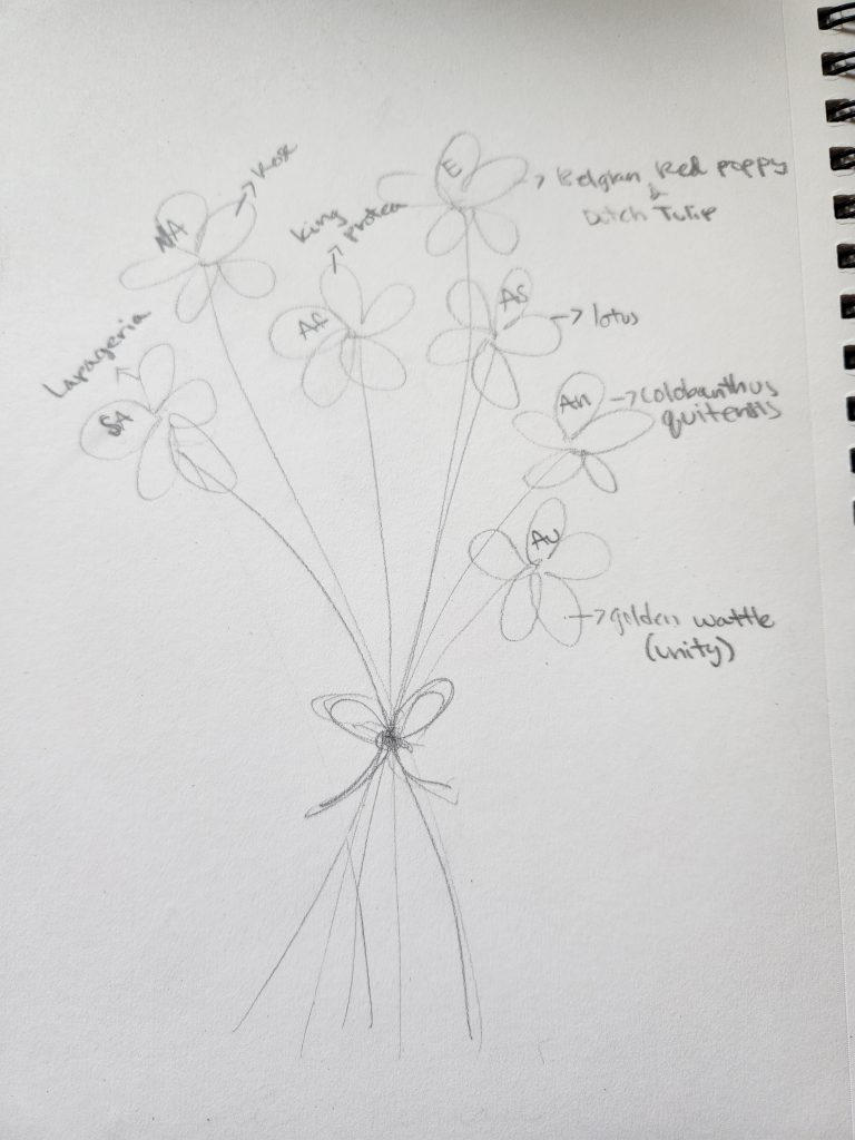
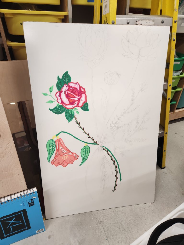
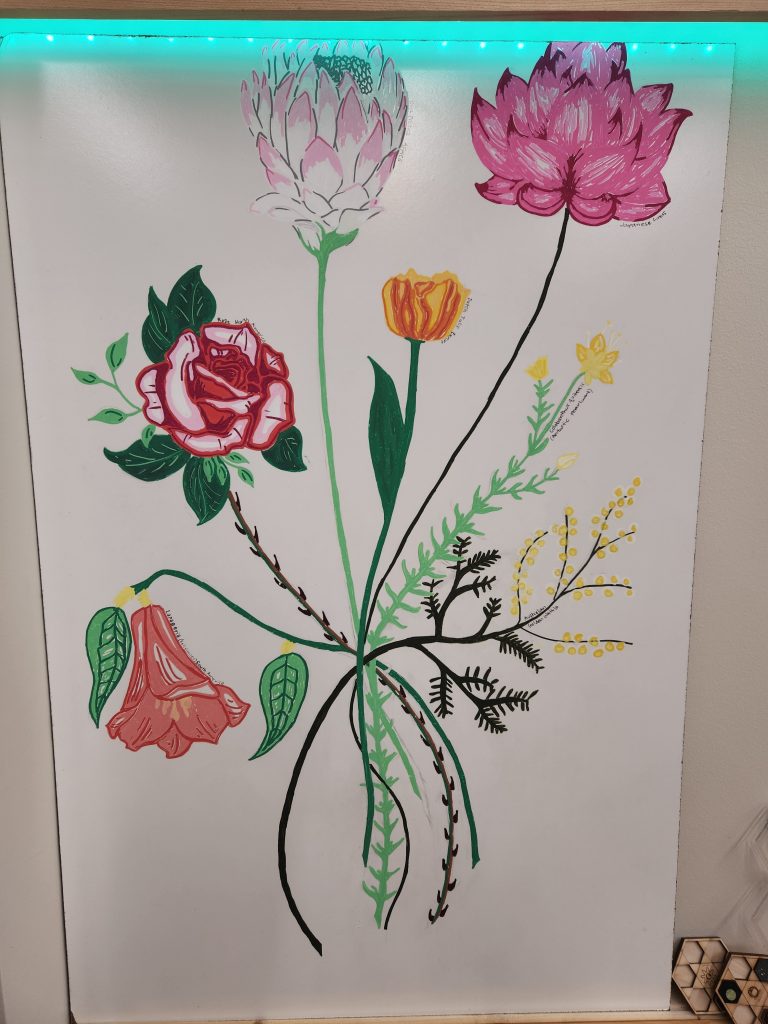
intercontinental bouquet painting
For my makerspace project, I am using an old whiteboard to create a painting. The painting is of a bouquet of flowers. Specifically, seven flowers, each one representing the symbolic flower of each continent. The bouquet is intended to symbolize unity amongst the earth and amongst different cultures. After eliminating multiple medias (because they weren’t applicable on the whiteboard), I ended up using paint pens to color the bouquet. After painting the flowers, I annotated them with the continent they represent.
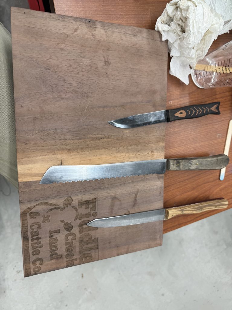
Makerspace interim
For my Makerspace project I decided to make a chess board but that turn out so I switch over to a magnetic knife board with the wood that was for the chessboard. The first step to making was cutting the wood on the table saw then I laser cut my family’s farm logo on the front. Then I decided the holes that were going to drilled into the back to hold the magnets. Next I loaded the file up on the CnC machine and cut it out then I filled the holes the holes with a small amount of epoxy and place the magnet. I put the epoxy in so it would hold the magnets in place. Then it was complete. It is tied into the international interim because I am going to put Japanese style knives on it and display them also the knife with fish design is a knife made by morakniv which is a Swedish company.
here is a picture
iPhone 5 teardown diagram
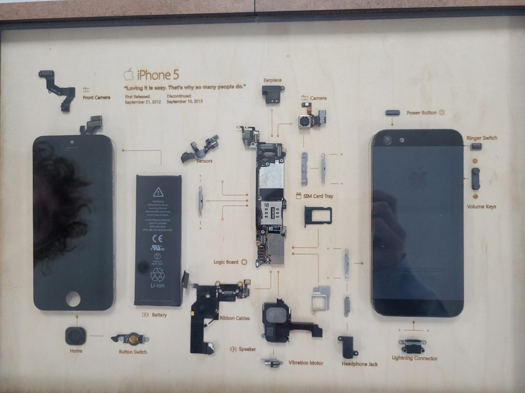
I Helped Peter with his project which is this teardown diagram of an iPhone 5. I helped with some of the gluing of the frame, the teardown of the phone, and other various steps. The way that this project is international themed is the phone was made in foreign countries such as China, Japan, and Taiwan, and then it was designed in Apple in California.
Bridging Cultures: Crafting a Paper Flute Experiment
Title: Bridging Cultures: Crafting a Paper Flute Experiment
Recently, I decided to try something unique: making a flute out of three pieces of A4 paper. Inspired by creativity and innovation worldwide, I followed tutorials from different corners of the globe to fold the paper into shape.
However, when I tried to play it, all I heard was the sound of rustling paper. Despite this, the experience taught me valuable lessons about patience and the importance of trying new things.
While my paper flute didn’t turn out as expected, the journey reminded me of the universal language of creativity and the joy of exploring ideas across borders. It’s a small experiment, but it speaks volumes about the beauty of global collaboration and the endless possibilities that come with it.
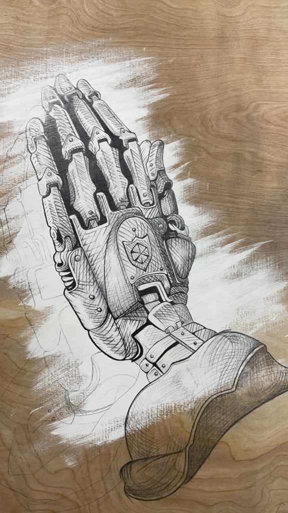
Prayer Hands
For my makerspace project I decided to work on prayer hands that I left unfinished the last interim week. Searching on Pinterest for nearly five minutes I had come across a take on prayer hands -I myself am not religious, but if the art piece seems challenging in any sense at times it sparks my interest. Sketching and marking the art out took little to no time, shading is the only thing that is taking much longer than anticipated. I assume at some point I’ll have to take the board home to finish it, and if it is pretty enough I might just keep it at home instead of keeping it in the Makerspace like intended.
Recent Comments